
Leakage Rate: Standard < 1%


Typical L/180 for construction type service not active duty
L/240 less noticeable deflection
L/360 regular active walking surface, higher trafic
L/480 typical building floor, high trafic
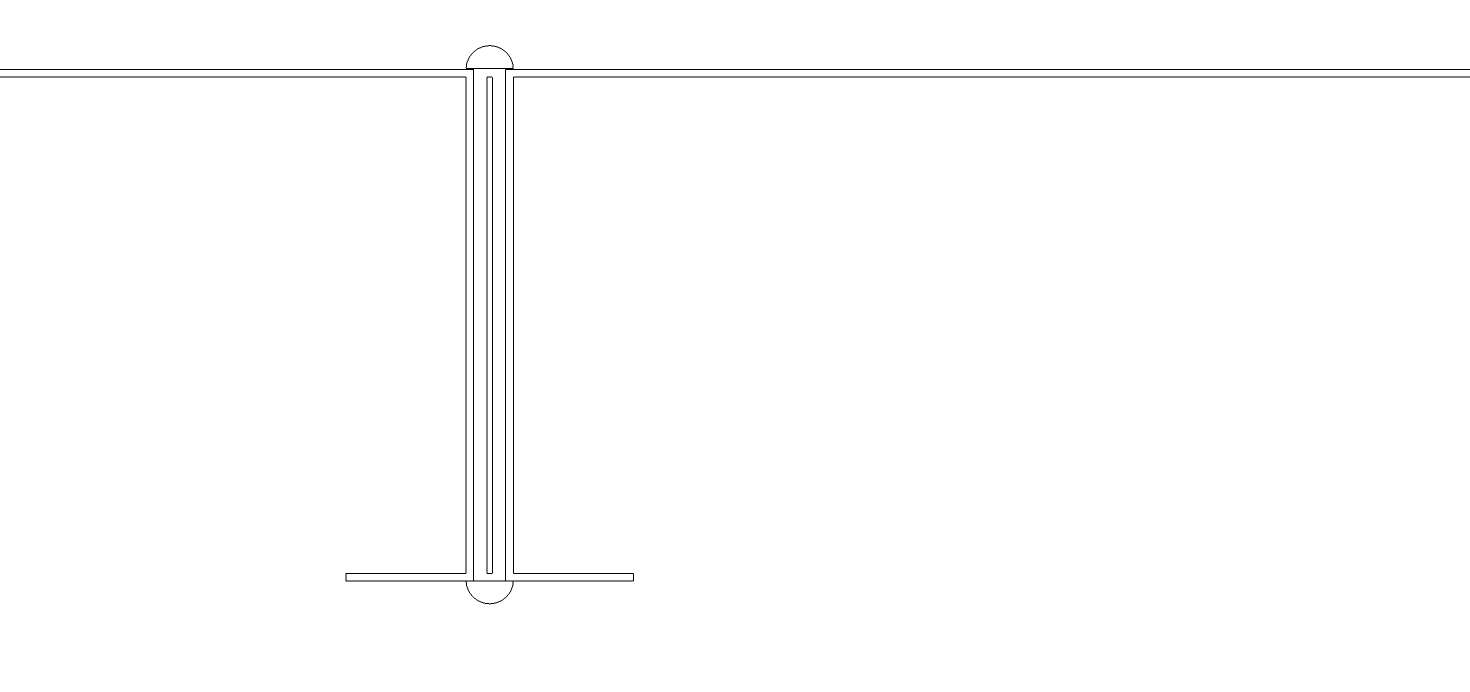
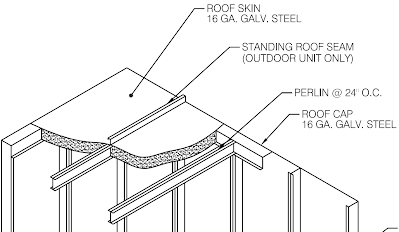
Roof Slope – Typically 2″ on most units. Target 1/4″ per foot for active water movement. Minimum 1/8″ per foot for minimal water pooling. Standing seam design provided for removing water leakage. Slope away from door access side of unit.
Trucking – 144″ wide or less, wider results in shipping splits. Typically 114″ tall or shorter, 126″ is easy to accommodate with step deck trailer and 146″ tall is possible with shorter splits on double drop. Most standard flat bed trucks are about 50′ long (114″ tall airhandler only).
Weights Rule Thumb –
Base & Roof: 21.43 lbs / sqft on most units – 18.43 lbs / sqft on smaller units (~ < 10,000 cfm and < 8′ wide). This is a rule of thumb and can change based on structural requirements. Exterior Walls: 6.3 lbs / sqft Interior Walls: 4.1 lbs / sqft Door: 12 lbs / sqft + 10 lbs Filter Rack: 1.43 lbs / sqft Drain Pan: 9.6 lbs / ft of width + (intermediate drain pans) * 10.59 / ft of width + Dampers, Louvers, Curb, Coils, VFDs, Fans, Filters, Electrical, etc.
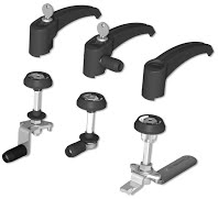
Door design – The Door must be very rigid to avoid bending or racking. This is critical to avoid leaking around door corners and edge. Doors should always try to be designed to swing into air pressure. This is critical for safety reasons and to minimize air leakage. Doors over about four feet in height or 30″ in width will typically require structural stiffeners inside of door. These stiffeners will help keep door stiff between hinges and handles. Doors over six feet tall will typically require three handles. Heavy duty hinges typically are required and must be re-enforced into airhandler walls. One risk of piano hinges is bending of rod and loss of functionality. Doors are sealed with automobile grade bulb seal on both exterior panel and interior panel surface. Two seals / double bulb seal provides minimal leakage around door. Doors available with hermetically sealed glass window for minimal heat loss. Glass provided with internal metal wiring for structural reenforcement.
18″ wide door needs 24″ between components
24″ wide door needs 30″ between components
30″ wide door needs 36″ between components
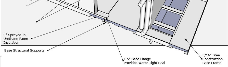
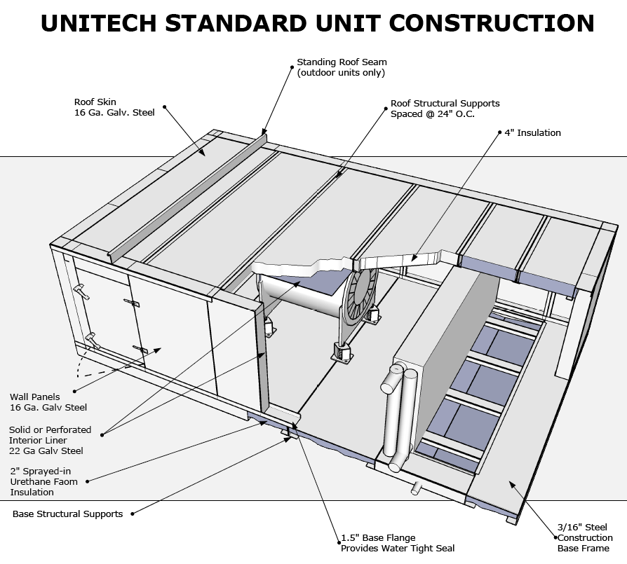
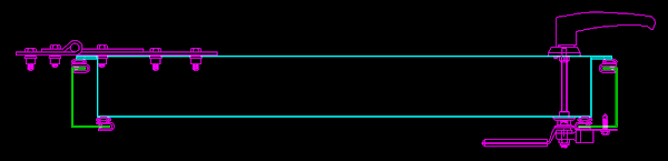
Base construction – Provided with structural beams as needed for typical L/180 deflection (L/240+ available). Standard is .36″ web and 7 ga walking surface. Walking surface covered with unitech standard “grip guard” finish for slip resistant walking surface. Bottom of base is covered with polyurethane foam. Foam provides thermal resistance barrier and is closed cell for final finish. Structural Supports added under mechanical equipment anchoring points. Base provided with 1.5″ water flange around perimeter for water tight construction. Auxiliary drains provided as needed. Bases are laser leveled before walls and components are added to remove racking issues when mounting units.
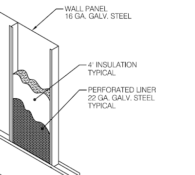
Wall / Roof construction – 16 Ga outer skin, 22 ga inner skin. Each joint is sealed with sika flex, externally, internally and across the seal. Walls are also re-enforced as needed for larger spans or for higher pressures.
Unit finish: Standard g90 galvanized finish for indoor units and powder coat finish for exterior units. Standard unit finish on outdoor units is 2,000 hour powder coat or 4,000 hour powder coat. Optional 7,000 hour powder coat exterior / interior finish available. Optional Aluminium interior finish available. Openings: Typically sized for 1200 fpm.
Openings: available as needed for inlet / outlet / bypass etc. High Efficiency takeoffs available for high velocity openings, ie 3,000 fpm. Units constructed to pass 1% leakage rate testing by standard. Testing available at factory or onsite as needed. Common onsite leakage is due to controls penetrations in unit casing, pipe penetrations, difficulty in sealing sa / ra openings for testing.
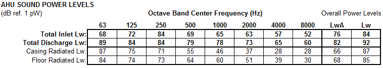
Sound: Consider the following airhandler desinged both with singlewall and doublewall construction
4″ Doublewall
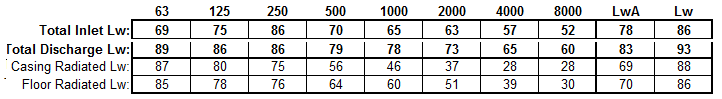
2″ Doublewall
Consider heat loss through airhandler q=k*A*dT/dX k => R value of 16
A = assume fixed
dT = assume fixed
dX = thickness of insulation
4″ wall 1/2 heat loss as 2″ wall
R value of 16 1/2 heat loss as R value of 8