
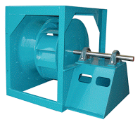
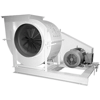
Plenum Fan, Arrangement 1 shown
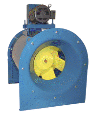
Arrangement 3
Mounting:
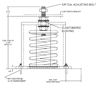
2″ deflection seismic housed (adds 7″ to fan height) (Height Saver Bracket Reduces 7″ to 1″)
minimum 125 lbs / spring to load spring ~ size 30″ wheel
1″ deflection spring
minimum 50 lbs / spring to load springs ~ size 18″ wheel
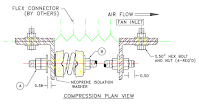
Thrust
Thrust = Fan Inlet Diameter x Fan TSP x 0.036 in
Rule thumb Thrust / Total Fan weight ~ > 10% (if greater than 10% should use)
Options
Inertia base – larger fans for vibration / sound sensitive applications
Piezometer Rings – Airflow measuring systems
Arrangements – Direct Drive, Belt Driven, Mix Flow, Modular Plenum, Vertical Shaft Plenum, SWSI, DWDI etc.
Inlet Isolation – Manual isolation panel, Backdraft Damper, Control Damper
Thermal Overload Panel – Used to individually fuse and protect each fan motor connected to a common VFD.
Pressure Relief Doors – Used on fan septum wall to allow bypass for airflow in even of system over pressurization.
Design Considerations
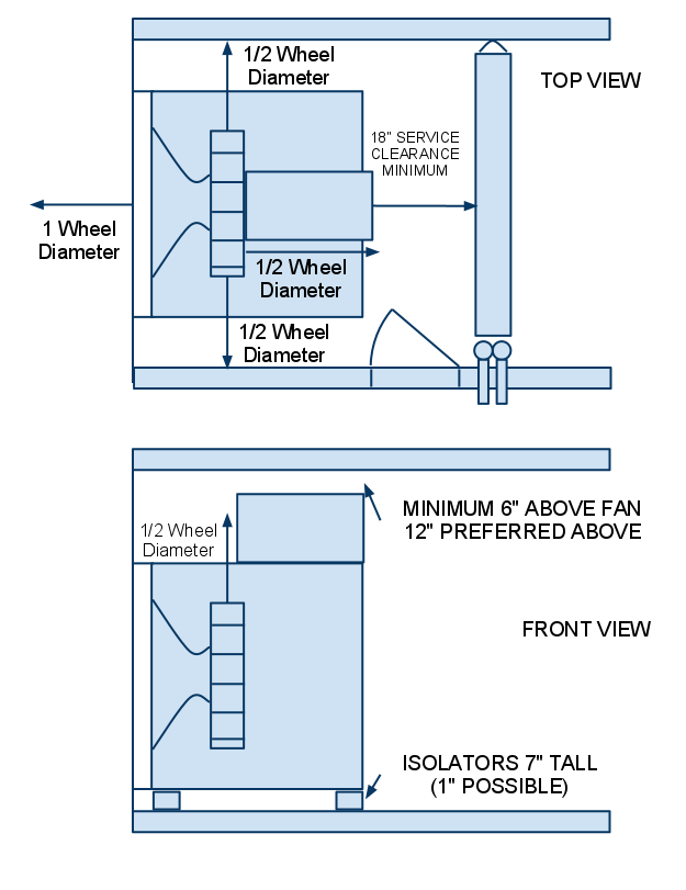
1 Wheel diameter free clearance upstream of fan. For example size 60 fan would have a 60″ wheel diameter and 60″ free upstream of fan.
1/2 Wheel diameter side to side of fan for plenum type fans. For example size 60 fan would have a 60″ wheel diameter and require 120″ free clearance. Typically need same 1/2 wheel diameter above fan for performance. Ideally, also require 1/2 wheel diameter below fan inlet, not always piratical. For applications where 1/2 wheel clearance is maintained upstream, side to side and top but not bottom, performance reduction is ~ 1% range.
1/2 Wheel diameter downstream. Distance is measured from actual wheel, not fan to next object. Fan assembly typically is of length about 80% of 1/2 wheel diameter. Maintain at least 18″ downstream of fan assembly to next object for service clearance.
The 1/2 Wheel diameter clearance is already accounted for on Modular Fan design. Modular fans can be stacked side to side, top to bottom without need for extra clearance.
Derate: dP = K * air density * (CFM / Net Area / 1097 ) ^2
Where
K = 1.8 * [(Wheel Diameter + 2 * Side Clearance ) / (2 * Wheel Diameter)] ^2
Note: (Wheel Diameter + 1 * Side Clearance ) / (2 * Wheel Diameter) >= 2 has a derate of 0
Net Area = (Wheel Diameter + 2 * Side Clearance ) ^2 – Wheel Area
Service: Typically maintain a minimum of 18″ on sides of fans, 6″ above fan, 18″ downstream of fan for service clearance. These are typically bare minimum and often overridden by clearance requirements. On small fans, these values can be replaced with a fan kill switch tied to access door and removal of guards around fan.
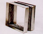
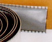
Rigid flex connector
Safety
Inlet Screen – barbecue grill style inlet screen that nests in the inlet funnel for protection on non-ducted inlets
Belt Guard – Provides protection to personnel from the moving drive parts.
Protective Enclosure – Grill style protective enclosure completely encloses all sides of the back of the fan wheel. Sides are individually removable and provide access to wheel.
Motor Removal Beam – Provided for larger motors to support motor weight while removing motor.
Mulitple Fans Combined (Array)
Thermal Overload Panel – Protect and isolate each fan from motor overload, add contactor for controls to be able to sense fan failure. Add over current and overload manual motor starter to protect each motor. Individual motors can be combined into single connection point for single vfd. VFD can be provided with redundant vfd package for continual non intrupt service in event of vfd failure.
Ceramic bearings or shaft grounding kit. When multiple fans (ie 4 or more), are used you need to include a shaft grounding kit. This will protect the motors from failing due to electrical arching through bearings that pits bearings and cuases prematuer failure.
Typically design around 7-1/2 hp or less
n-1 redundant design often available for 100% capacity in event of single fan failure
Must consider either backdraft dameprs on each fan or a blank off plate to isolate a single fan in event of fan failure.
Typically, springs are not required but are available on sensitive applications. Fans in this type application are fine balanced and installed with large mass around fan to absorb vibration. First 1/3 octive band of sound is typically significantly less on this type application vs traditional. other octive bands are typically the same.
Sample Cutsheet on Isolator
Sample Isolator Transmissibility